[Top] [Table Of Contents] [Prev] [Next] [Index]
4 out of 8 total pages
Installing and Working with the
Redundant System Manager Module 1
- This chapter provides the following installation, configuration, troubleshooting, and maintenance information for the redundant system manager module (RSMM) on the PortMaster 4:
Redundant System Manager Module Description
- You can install a redundant system manager module in the PortMaster 4 chassis to provide system manager backup. The manager modules must be installed in slots 4 and 5 and must be physically identical to each other. One, usually the module in slot 4, functions as the primary manager, and the backup module is called the secondary manager.
Overview of Redundant Manager Operation
- By installing a redundant system manager module, you can prevent PortMaster 4 downtime due to manager module failure. With two manager modules installed, if the primary manager fails, the secondary manager takes over. Although all active calls are dropped during failover to the secondary manager, power to the entire system is never interrupted and call traffic resumes as soon as the secondary manger takes over as primary and resets the individual line boards.
- When operating the PortMaster 4 with a single manager module, you must install the module in slot 4. You install the backup manager module in slot 5. When you boot the system for the first time, the module in slot 4 starts up as the primary manager and the module in slot 5 starts up as the secondary. (See "Primary Manager Module Selection at Startup" on page 1-18 for details.)
- Each system manager module consists of a manager board and an Ethernet 10/100Mbps board. The manager board manages and administers the installed line boards. The manager board communicates with installed line boards at 155Mbps speeds through an embedded Asynchronous Transfer Mode (ATM) cell-switching network linked to the chassis' passive backplane. Manager modules communicate with each other via a 115Kb universal asynchronous receiver/transmitter (UART) channel.
Physical Characteristics of a Manager Module
- Each manager module provides the following (see Figure 1-1):
- C0 port--for a console connection with a null modem cable or for an asynchronous connection to an external modem
¯ The green LED on the C0 port is illuminated when the manager module is the primary manager, and not illuminated when it is the secondary manager
¯ The green LED on the C0 port blinks when the manager module has not yet determined if it is the primary or secondary manager
¯ The amber LED on the C0 port is illuminated when it receives a message from the other manager module
- C1 port--for an asynchronous connection to an external modem
- Ether0 interface--10BaseT Ethernet interface for a private LAN connection
- DIP switch 1 (bottom) and 2 (top)--to set C0 function and the boot mode of the manager card
- Ether1 interface--10/100BaseT Ethernet interface for an upstream Ethernet connection
- Media-independent interface (MII) connection--alternative Ether1 interface that accepts optional adapters for connection to copper or optical media
- DIAG LED--lights when the module is booting and blinks off every 5 seconds during normal operation
- PWR LED--remains solidly lit when the module is receiving power during normal operation
Figure 1-1 System Manager Module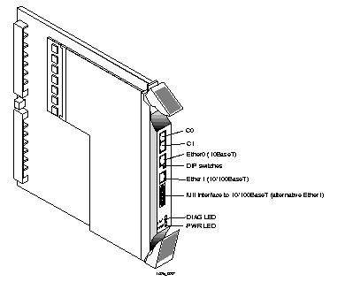
Installation and Configuration Requirements
- To install and configure a redundant system manager module, you must have the appropriate hardware and software and must take the proper safety precautions.
Verifying Hardware and Software for Redundant Operation
- Before installing and configuring the redundant manager module feature on your PortMaster 4, make sure of the following:
1. Verify that your PortMaster 4 chassis has the Revision C backplane.
Check the backplane for the revision letter C . The revision letter is located behind slot 2.
2. Make sure that both system manager modules are capable of redundancy.
Verify that the model number on each module ends in R . Or check the label on the box that each module was shipped in for a manufacture date after July 1999 .
3. Verify that both system manager modules have ComOS 4.2 loaded.
Warning ¯  Use of a version earlier than ComOS 4.2 can damage PortMaster 4 hardware.
Safety Precautions
Warning ¯  (DC models only) Before working on equipment that is connected to power lines, remove jewelry such as rings, necklaces, and watches. Metal objects will heat up when connected to power and ground and can cause serious burns or weld the metal object to the terminals.
- If an electrical accident occurs, turn off the emergency power switch for the room in which you are working, cautiously unplug the system's power, and get medical assistance for any injured person.
Warning ¯  To avoid damaging the internal components of the PortMaster 4, follow antistatic precautions by wearing a grounding wrist strap.
Grounding Wrist Strap Instructions
- When working with the internal components of the PortMaster 4, you must wear a grounding wrist strap. Grounding wrist straps can be attached either at the front of the chassis behind the power bay door, or at the back of chassis in the lower right and left corners.
- Figure 1-2 shows the proper place to attach a grounding wrist strap at the front of the chassis.
Figure 1-2 Grounding Strap Attachment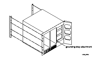 --Front Panel
- Figure 1-3 shows the proper places to attach a grounding wrist strap at the back of the chassis.
Figure 1-3 Grounding Strap Attachments--Rear Panel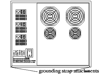
Installing a Redundant System Manager Module
- Follow these instructions to install the redundant manager module.
1. Line up the edge of the module with the card guide in slot 5 (Figure 1-4).
Note ¯  The physical slots are numbered 0 through 9 from left to right. Although a manager module is physically installed in slot 4 or slot 5, the Ethernet board of the module functioning as the primary manager is monitored through virtual slot 10.
2. Insert the manager module in slot 5, gently guiding the module into the slot.
If you have trouble sliding the module into the card guide, gently wiggle it back and forth to help it slide in.
Figure 1-4 Installing the Redundant System Manager Module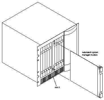
3. When the module is completely inserted in the slot, close the top and bottom tabs so they are flush with the face of the chassis.
Closing the tabs causes the module to connect with the backplane.
DIP Switch Settings
- The DIP switches on each manager module are located between Ether0 and Ether1 (see Figure 1-5). Each switch is off when turned to the left, and on when turned to the right.
- Figure 1-5 shows the location of the DIP switches on the manager module.
Figure 1-5 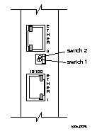 DIP Switches
Connecting a Console
- Because the console port is your primary connection to the manager module, Lucent strongly recommends that you connect a PC or terminal to the console port on both the primary and secondary manager modules. Follow these instructions to connect a PC or terminal to a PortMaster 4 manager module for use as a console. You can use the console connection on each manager module to configure and manage the PortMaster 4.
Required Equipment
o If you are using a PC, a RJ-45-to-DB-25 console cable with a 25-to-9-pin female adapter (See "Console Cable" on page A-2 for more information.)
o PC or terminal
Procedure
1. Remove the cover from the cable guide if necessary.
2. Run the end of the cable with the RJ-45 connector through the cable guide duct until it is directly over the manager module.
3. Pull the end of the cable with the RJ-45 connector through the fingers of the cable guide duct as shown in Figure 1-6.
Figure 1-6 Pulling a Cable through the Cable Guide
4. Attach the RJ-45 connector to the C0 or C1 port of the manager module (see Figure 1-7).
Figure 1-7 Asynchronous Ports on the System Manager Module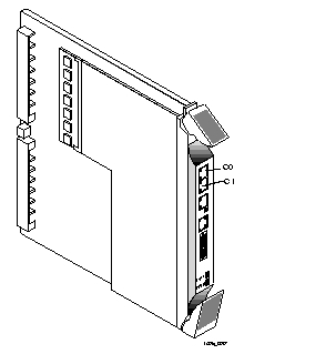
5. Attach the RS-232 end of the cable to a dumb terminal or computer running terminal emulation software.
6. If you have finished inserting modules and boards and connecting lines, replace the cable guide cover by squeezing the duct fingers together with one hand, and sliding the cover over the duct fingers with the other.
7. Ensure that DIP switch 1 on the manager module is turned to the left.
8. Set the PC or terminal to 9600 baud, 8 data bits, 1 stop bit, a parity of none, and software flow control on (XON/XOFF).
(Optional) Connecting an External Modem
- Follow these instructions to connect an external modem for remote administration and troubleshooting.
Required Equipment
o RJ-45-to-RS-232 modem cable (See "Modem Cable" on page A-1 for more information.)
o External modem
Procedure
1. Remove the cover from the cable guide, if necessary.
2. Run the end of the cable with the RJ-45 connector through the cable guide duct until it is directly over the manager module.
3. Pull the cable through the fingers of the cable guide duct as shown in Figure 1-8.
Figure 1-8 Pulling a Cable through the Cable Guide
4. Attach the RJ-45 end of the cable to the C0 port of the manager module (see Figure 1-9).
Figure 1-9 Console Port on the System Manager Module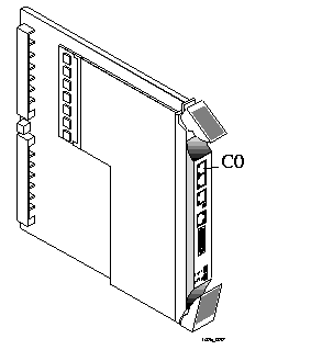
5. If you have finished inserting modules and boards and connecting lines, replace the cable guide cover by squeezing the duct fingers together with one hand, and sliding the cover over the duct fingers with the other.
6. Ensure that DIP switch 1 is turned to the right.
7. Attach the RS-232 end of the cable to the external modem.
Refer to the documentation that came with your external modem for information on how to attach the RS-232 cable.
Connecting an Ethernet Cable
- The PortMaster 4 supports the following Ethernet connections on each manager module:
- 10/100BaseT--used as the primary uplink. This Ether1 interface is located on the Ethernet board but powered from the manager board. It is used for syslog , traceroute , Telnet, RADIUS, ChoiceNet, the Domain Name System (DNS), and TFTP.
- 10BaseT--used for private network management. This Ether0 interface is physically located on the manager board.
- Media-independent interface (MII)--used to connect other wiring types (copper or fiber, for example) to the 10/100BaseT Ethernet. Devices attached to the MII interface must be MII-compliant.
- Lucent strongly recommends that you configure and connect lines to both Ether0 and Ether1 interfaces on each manager module. These interfaces must be on different Ethernet subnetworks.
- However, because Ether1 interface on the redundant manager inherits its IP address from the primary manager, be sure to connect the Ether1 interface on the redundant manager to the same subnetwork as the Ether1 interface on the primary manager module. (See "Configuring the Ethernet Interfaces" on page 1-15.)
Ethernet 10/100BaseT
- When using a PortMaster 4 with a redundant system manager module, you must configure the Ether1 interface on both manager modules. The Ether1 interface has the following characteristics and functions:
- Resides on the Ethernet board, which receives power from the manager board. The Ethernet board and the manager board make up the manager module
- Communicates with the manager board over the PortMaster 4's passive ATM backplane
- Contains a CPU for inbound data and a CPU for outbound data
- Remains active during low power or excessive heat conditions
- Is generally used to carry network traffic
Note ¯  The PROM of the Ethernet card attached to the manager module contains the MAC address, which is actually a MAC address range. Conceptually, the Ethernet card has the MAC address, and MAC addresses for other devices in the system are software assigned from the address range based on the Ethernet card's MAC address. The primary manager in slot 4 assigns MAC addresses immediately after bootup. During failover, system components retain the MAC address assigned by the primary manager in slot 4.
- Follow these instructions to connect an Ethernet cable to the Ethernet 10/100BaseT interface
- One of the following:
o Category 5 twisted pair cable, as specified by the EIA/TIA-568-B wiring standard, with an RJ-45 connector (See "RJ-45 Cable" on page A-2 and "Ethernet Cable Specifications" on page A-3 for more information.)
o MII cable with an MII connector
Procedure
1. Remove the cover from the cable guide, if necessary.
2. Run the cable through the cable guide duct until it is directly over the manager module.
3. Pull the cable through the fingers of the cable guide duct as shown in Figure 1-10.
4. Connect the cable to the RJ-45 or MII Ethernet 10/100BaseT interface (see Figure 1-11).
If both interfaces are connected, the system uses the MII by default.
5. If you have finished inserting modules and boards and connecting lines, replace the cable guide cover by squeezing the duct fingers together with one hand, and sliding the cover over the duct fingers with the other.
Figure 1-10 Pulling a Cable through the Cable Guide
Figure 1-11 Ethernet 10/100BaseT Interfaces on the Redundant Manager Module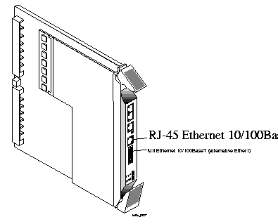
Ethernet 10BaseT
- Because you communicate with the system manager modules over the network via the Ether0 interfaces, Lucent strongly recommends that you configure Ether0 on both manager modules when operating the PortMaster 4 with a redundant system manager module.
- Follow these instructions to connect an Ethernet cable to the Ethernet 10BaseT interface of the redundant manager module.
Required Equipment
o Category 5 unshielded twisted pair cable, as specified by the EIA/TIA-568-A wiring standard, with an RJ-45 connector (See "RJ-45 Cable" on page A-2 and "Ethernet Cable Specifications" on page A-3 for more information.)
Procedure
1. Remove the cover from the cable guide, if necessary.
2. Run the cable through the cable guide duct until it is directly over the manager module.
3. Pull the cable through the fingers of the cable guide duct as shown in Figure 1-12.
Figure 1-12 Pulling a Cable through the Cable Guide
4. Connect the cable to the Ethernet 10BaseT interface (see Figure 1-13).
Figure 1-13 Ethernet 10BaseT Interface on the Manager Module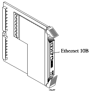
5. If you have finished inserting modules and boards and connecting lines, replace the cable guide cover by squeezing the duct fingers together with one hand, and sliding the cover over the duct fingers with the other.
Configuring a Redundant System Manager Module
- Before following the instructions in this section, you must have installed a redundant system manager module in slot 5 of a fully configured, functioning PortMaster 4. Use the following procedure to copy the PortMaster 4 system configuration to a redundant manager module:
1. Review "Installation and Configuration Requirements" on page 1-3 to make sure you are ready to configure.
2. Connect to the primary manager module in slot 4 via the console or an Ethernet port and enter the following command:
Command> save all
This command copies the system configuration from the primary manager module to the redundant (secondary) manager module's nonvolatile memory.
- You can now configure the redundant manager's Ethernet interface.
Configuring the Ethernet Interfaces
- When you install a redundant system manager module in a fully configured, functioning PortMaster 4, you need to configure only the Ether0 interface on the redundant manager. The redundant manager inherits its Ether1 interface IP address from the Ether1 interface of the primary manager during failover.
- The IP address you assign to the Ether0 interface on the redundant manager can be in the same subnet as the Ether0 address on the primary manager, but Ether0 addresses for either manager module must be in a different subnet than the address of the Ether1 interface. See Chapter 4, "Configuring an Ethernet Interface," in the PortMaster 4 Configuration Guide for a complete discussion of Ethernet interfaces.
- Use the following procedure to assign an IP address to the redundant manager and activate the configuration:
1. Connect to the secondary manager in slot 5 via the console port and use the following command to assign an IP address and netmask:
Command (Secondary)> set Ether0 address Ipaddress [/NM] [Ipmask]
To communicate with the redundant module on the network, you must assign it an IP address.
2. Enter the following commands to activate the configuration:
Command (Secondary)> save all
Command (Secondary)> reboot secondary
The save all command, entered on the redundant manager, saves the configuration to nonvolatile memory on the secondary manager.
When using a redundant manager, entering the save all command on the primary manager console saves the configuration to nonvolatile memory on both manager modules.
3. Use the commands in Table 1-1 as necessary to configure and operate the redundant manager module.
Refer to Chapter 3, "ComOS 4.2 Commands," for a detailed description of each command.
Note ¯  The redundant manager always displays (Secondary) in the prompt. You can observe in the logs how the prompt shifts from one manager to the other when they change roles.
Table 1-1 Redundant Manager Module Configuration Commands
|
Action
|
Command Syntax
|
Event
|
|---|
| Update the secondary manager with the current system configuration.
| Command> save all
| This command entered on the primary manager copies the system configuration to the secondary manager.
|
| Save configuration information to the primary or secondary manager.
|
· Command> save Keyword local-only
· Command> save Keyword peer-also
| Using local-only saves configuration information to the manager module you enter it from.
From the primary manager only, peer-also saves to both modules. You cannot use this keyword from the secondary manager module.
|
| Configure an Ethernet address on the secondary manager.
|
· Command> set ether0 address Ipaddress
| This command activates the secondary manager module on the LAN.
|
| Update ComOS on the secondary manager.
| Command (Secondary)> tftp get Ipaddress Filename local-only
| This command downloads ComOS from the local TFTP server and saves it to nonvolatile memory on the secondary manager module.
|
| Copy a line card executable file to the redundant manager. You can also copy configuration files.
| Command> copy /Subdirectory/Filename(source) peer:[/Subdirectory/Filename
(destination)]
| With two managers, the PortMaster 4 has two separate file systems. Use the copy peer command to copy an executable file from the primary to the secondary manager. For example:
copy /shared/quadt1 peer:
|
| View manager module status.
| Command> show smm-backup
| This command displays information about the primary and secondary manager modules.
|
| Name the redundant manager module.
| Command> set altname Hostname
| This command sets the prompt for the manager module in slot 5.
|
| Reboot the PortMaster 4.
| Command> reboot system
| This command reboots the entire system. You can enter this command from either manager. This is the highest-level reboot command.
|
| Reboot the secondary manager.
| Command> reboot secondary
| This command reboots the secondary manager module and can be entered from either module. Rebooting the secondary manager does not affect the current operating parameters of the system. It just ensures that the secondary manager is running the current code and that its configuration is up-to-date.
|
| Reboot the current manager module.
| Command> reboot me
| If you enter this command on the primary manager, it disconnects all calls and shifts the primary responsibility to the secondary. If you enter this command on the secondary, it reboots the secondary and has no effect on current PortMaster 4 operation.
To better understand the reboot commands, note the defaults:
· Entering reboot without an argument from the primary manager reboots the entire system--just like the reboot system command.
· Entering reboot without an argument from the secondary manager reboots only the secondary.
|
| Reboot the secondary manager.
| Command (Secondary)> reset secondary
| This command is an alternative way to reboot the secondary manager. It has the same effect as the reboot secondary command.
|
| Reboot the primary from the secondary
| Command (Secondary)> reset slotSlotnumber
| Entering this command is the only way you can reboot the primary manager from the secondary manager. You can also reboot the secondary from the primary with the reset slot command.
|
| Debug the connection between the primary and secondary manager modules.
|
· Command> set console
· Command> set debug m2m
| These commands display the messages sent over the UART channel between the primary and secondary manager modules to the screen of your console session.
|
· Command> set debug off
· Command> reset console
| These commands turn debug mode off and redirect all debug output to null.
|
Primary Manager Module Selection at Startup
- The PortMaster 4 uses the following criteria for primary manager module selection when you turn on the unit:
1. A manager module is primary if it does not encounter another manager module for 4 seconds during the boot-up process.
2. If two manager modules boot at the same time, the manager in slot 4 is primary and the manager in slot 5 is secondary.
- After boot-up, the secondary manager sends hello messages at 1-second intervals to the primary manager and the primary manager responds.
- See "Handling System Manager Module Failure" on page 1-22 for information about manager module failover and replacement.
SNMP Alarms Supporting Redundancy
- The SNMP alarms shown in Table 1-2 have been added for events related to the redundant system manager module feature. These alarms are valid for either slot 4 or slot 5. When slot 5 is primary, the slot numbers in the message are reversed.
Table 1-2 SNMP Alarms for Redundant Manager Module Events
|
Alarm
|
Description
|
|---|
| Slot 4 becoming primary manager.
| This alarm, reported by the primary manager, is generated when a system manager module recognizes itself as the primary manager. This event can take place after the bootup decision process or after a failover has occurred.
|
| Slot 5 becoming secondary manager.
| This alarm, reported by the secondary manager, is generated when a system manager module recognizes itself as the secondary manager.
|
| Primary manager in slot 4 failed.
| This alarm is generated by the secondary manager module after it fails to get a response to its hello messages for 5 seconds--five hello messages are ignored by the primary manager module.
|
| Secondary manager in slot 5 failed.
| This alarm, reported by the primary manager, is generated when the primary manager does not receive hello messages from the secondary for 30 seconds.
|
| Secondary manager detected in slot 5.
| This alarm is generated by the primary manager module when it detects a secondary manager module in slot 5. This alarm conveys the same information as "Slot 5 becoming secondary manager," except that it is reported by the primary module.
|
| Can't hear manager in slot 4.
| This alarm is generated when the communication between managers fails. The manager module in slot 5 determines that the manager in slot 4 is still running because it can still detect a heartbeat.
|
Using PMVison 1.8 with a Redundant System Manager Module
Note ¯  Be sure to use PMVision 1.8 on a PortMaster 4 with a redundant system manager module. Earlier versions of PMVision and the older programs pminstall , PMconsole, and PMconsole for Microsoft Windows do not recognize the redundant system manager module feature and view each manager module in the PortMaster 4 as a separate system.
- PMVision automatically handles both system manager modules transparently. If you connect to a PortMaster 4 using the Ether0 interface of the manager module in either slot 4 or slot 5, PMVision automatically contacts both managers and determines which is primary. You can display information about both managers by selecting the Configure Æ Boards option.
- Figure 1-14 shows a display for a PortMaster 4 with a redundant manager module. For more information about PMVision, see the PMVision User's Guide.
Figure 1-14 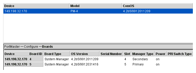 PMVision Showing a Primary and Secondary Manager
Configuring Manager Information
- You can set the IP address for the Ether0 port of either manager by double-clicking the desired manager module name and clicking the Ethernets button on the resulting display. Lucent recommends that you issue a reboot command using the Command option after changing the IP address.
- You can also set the system name for each module by selecting the Configure Æ Global option.
Downloading an Image of ComOS
- The ComOS for both modules can be updated simultaneously. In PMVision, select Maintain Æ Upgrade to perform the update. Enter or browse to the location of the ComOS image, and click the Update button.
Troubleshooting a Redundant System Manager Module
- When troubleshooting a redundant manager module system, always verify that both manager modules are running ComOS 4.2 or later. A possible indication of an incompatible ComOS on one of the modules is a solidly lit amber C0 light.
- Table 1-3 identifies manager module LED behavior, possible causes of the behavior, and explanation or possible solution.
Table 1-3 Hardware Problems and Solutions on the Manager Module
|
LED Behavior
|
Possible Cause
|
Explanation or Possible Solution
|
|---|
| Green C0 LED is lit.
| Manager module is primary
| Normal behavior when a redundant manager module is installed.
|
| Green C0 LED off.
| Manager module is secondary
| Normal behavior when a redundant manager module is installed.
|
| Green C0 LED is flashing.
| Manager module is booting and negotiating with the other manager to determine which is primary.
| Normal behavior for a few seconds during bootup. Persistent flashing indicates trouble in the communications path between the two manager modules. See "Troubleshooting Communication between Manager Modules" on page 1-23.
|
| Amber C0 LED is flashing.
| Peer-to-peer messages are traveling between manager modules.
| Normal behavior when a redundant manager module is installed.
|
| All LEDs fail to light.
| Power is not present.
| Check the power switch, power cable, outlet, and fuse. For instructions on checking and changing the fuse in the AC version, see "Replacing a Fuse" on page 4-10 of the PortMaster 4 Installation Guide .
Contact Lucent NetCare technical support if power is not present on the DC version.
|
| Amber DIAG LED on the manager module does not light.
| Board malfunction.
| Contact Lucent NetCare technical support.
|
| During startup, the DIAG LED on the manager module fails to light, stays lit, or blinks three times per second continuously.
| A hardware problem has occurred.
| Contact Lucent NetCare technical support.
|
| During startup, the DIAG LED on the manager module blinks once per second for more than a minute.
|
· DIP switch 2 is turned to the left and no boot server is present.
· Nonvolatile RAM contents are corrupt.
|
· If no boot server is available, verify that DIP switch 2 is turned to the right and reboot; otherwise, see the network booting procedure in the PortMaster Troubleshooting Guide.
· If nonvolatile RAM contents are corrupt, follow the PortMaster Troubleshooting Guide procedure for network booting and rewriting the contents of nonvolatile RAM.
|
| Immediately after booting, the DIAG LED on the manager module stays solidly lit or does not light.
This behavior does not refer to the boot sequence, during which the DIAG LED is not lit for between 5 and 7 seconds.
| A component might have loosened during shipping.
| Remove the manager module from the PortMaster 4 chassis and verify the following:
· The SIMM is firmly seated.
· The nonvolatile RAM is firmly in place.
If all items have been verified and the problem is not fixed, refer to "Observing Boot Messages" on page 4-3 in the PortMaster 4 Installation Guide , and boot in console mode. If the boot messages do not suggest a solution, record the information and contact Lucent NetCare technical support.
|
| During operation, the DIAG LED on the manager module stays solidly lit or does not light.
| A hardware problem might have been caused by an external device.
| If the LED stays solidly lit or does not light after you have removed all external devices, contact Lucent NetCare technical support.
|
| No console login prompt is displayed.
| Terminal settings are incorrect or a connection or cable is inoperable.
|
· Verify terminal settings of 9600 baud, 8 data bits, 1 stop bit, a parity of none, and software control on (XON/XOFF).
· Verify that DIP switch 1 is turned to the left.
· Verify that you have a working console (null modem) cable and that it is properly connected at both ends. For cable information see "Console Cable" on page A-2.
|
| Link (green) LED on an Ethernet interface is not lit when connected to an Ethernet hub.
| There is no link integrity.
| Check the connection to the hub.
|
| Network (amber) LED on an Ethernet interface is solidly lit.
| Heavy traffic can cause the network LED to blink so rapidly that it appears to be solidly lit.
However; If packets cannot be passed, you might have an incorrectly cabled network.
| Verify that the network cabling is correct.
|
| Network (amber) LED on an Ethernet interface is not lit.
| If the PortMaster 4 is not receiving or sending traffic, the network LED is not lit.
| Verify that the network cabling is correct.
|
| An undefined problem occurred at startup, but the cause cannot be determined from LED behavior.
| Refer to the solution column.
| Try booting in console mode, and observe the boot messages. See "Observing Boot Messages" on page 4-3 of the PortMaster 4 Installation Guide . If the boot messages do not suggest a solution, record the information and contact Lucent NetCare technical support.
|
Handling System Manager Module Failure
- This section explains the failover process for the primary system manager module and provides instructions for troubleshooting communication between the manager modules, replacing a failed manager module, and upgrading a replacement manager.
Primary Manager Module Failover
- Primary manager module failover on the PortMaster 4 proceeds as follows:
1. If the secondary manager module does not receive responses to five consecutive hello messages, it listens for the heartbeat of the primary.
2. If it detects a heartbeat, the secondary does not take over as primary manager but generates a "Can't hear manager in slot 4." SNMP alarm.
3. If the secondary manager does not detect a heartbeat from the primary, it takes over and becomes primary.
4. The new primary manager reboots the system. All calls and network connections to the PortMaster are dropped, and dynamic routing information is lost.
- Heavy traffic on the primary manager can temporarily impede manager-to-manager communication. This normal condition can create a failover-like situation. See "Troubleshooting Communication between Manager Modules" on page 1-23 for details.
Troubleshooting Communication between Manager Modules
- A burst of heavy traffic on the primary manager can cause temporary loss of communication over the 115Kb UART communications channel between the primary and the secondary manager modules. This behavior can appear very much like a failover. To troubleshoot the UART channel for possible failure, follow this procedure:
1. Check for the following two events, which can indicate channel failure:
a. The secondary manager does not detect a heartbeat from the primary and generates a "Primary manager in slot 4 failed." SNMP alarm. If you can verify that the primary manager is functioning properly, proceed to Step 5. If the secondary generates a "Can't hear manager." alarm, proceed to Step 2.
b. The primary receives no communication from the secondary for 30 seconds and generates a "Secondary manager in slot 5 failed." SNMP alarm. (The primary does not check for the secondary's heartbeat.)
2. If you receive these failure alarms on both manager modules, wait and monitor the problem for several minutes.
3. If the problem persists for more than a minute or two, reboot the secondary manager module from the secondary's console.
4. If the reboot fails to correct the problem, turn power to the PortMaster 4 off and on.
5. If the manager modules are still not communicating, reseat the secondary manager module by pulling it out and reinserting it into the slot.
See "Safety Precautions" on page 1-4 and "Grounding Wrist Strap Instructions" on page 1-4 before proceeding.
6. If reseating the secondary manager fails to correct the problem, reseat the primary manager module.
7. If the communication problem persists, contact Lucent NetCare technical support.
Replacing a Failed Manager Module
- Redundant manager modules are shipped with ComOS 4.2 installed. When the active system manager module fails, the secondary manager takes over as the primary manager. To hot-swap the failed manager module with a new one, follow this procedure:
1. Make sure that you have the proper hardware and software, and take the proper safety precautions.
See "Installation and Configuration Requirements" on page 1-3 for instructions.
2. Disconnect lines to the failed manager module.
3. Open the top and bottom tabs on the failed manager module and remove it from the slot in the PortMaster 4 chassis.
4. Insert a new manager module.
See "Installing a Redundant System Manager Module" on page 1-5 for instructions.
5. Connect a console cable and Ether0 and Ether1 lines.
See "Connecting a Console" on page 1-7 and "Connecting an Ethernet Cable" on page 1-10.
6. Enter the following command to configure an Ethernet address for Ether0:
Command> set ether0 address Ipaddress
See "Configuring the Ethernet Interfaces" on page 1-15 for more information.
7. Enter the following commands to save changes to nonvolatile memory and activate the configuration:
Command> save all
Command> reboot secondary
Upgrading a Replacement Manager Module to ComOS 4.2
- This section describes how to upgrade a spare system manager module to ComOS 4.2 or later from the command line.
- You can also use PMVision 1.8 to upgrade the PortMaster 4.
Note ¯  Be sure to use PMVision 1.8 on a PortMaster 4 with a redundant system manager module. Earlier versions of PMVision and the older programs pminstall , PMconsole, and PMconsole for Microsoft Windows do not recognize the redundant system manager module feature and view each manager module in the PortMaster 4 as a separate system.
- Follow this procedure to upgrade a spare system manager module to ComOS 4.2 or later:
1. Make sure that you have the proper hardware and software, and take the proper safety precautions.
a. See "Installation and Configuration Requirements" on page 1-3 for instructions.
b. Make sure that the manager module in slot 4 is running ComOS 4.2. If it is not, upgrade this manager before going on to Step 2
2. Prepare the spare manager module for netbooting:
a. Set DIP switch 2 to the left.
See "DIP Switch Settings" on page 1-6 for more information.
b. Set up a directory structure to load ComOS 4.2 for netbooting to the manager's Ether0 IP address.
Procedures for netbooting are located at http://www.livingston.com/tech/technotes . Scroll to PortMaster Troubleshooting , click Netboot Procedures , then select the procedure for your platform.
3. Insert the spare manager module in slot 5.
See "Installing a Redundant System Manager Module" on page 1-5 for instructions.
4. Connect a console cable and Ether0 and Ether1 lines.
See "Connecting a Console" on page 1-7 and "Connecting an Ethernet Cable" on page 1-10.
5. Connect to the spare manager module.
6. If an IP address, netmask, and gateway address for the Ether0 interface are not provided by Dynamic Host Configuration Protocol (DHCP) services, enter the following commands to configure them:
Command> set ether0 address Ipaddress
Command> set netmask Netmask
Command> set gateway Ipaddress
Command> save all
See "Configuring the Ethernet Interfaces" on page 1-15 for more information.
7. Upgrade ComOS on the spare manager module to ComOS 4.2.
¯ You can use the tftp get command to download ComOS by entering the command as follows from the spare manager module:
Command> tftp get Ipaddress Filename
Replace Ipaddress with the IP address of the TFTP server and Filename with the name of the ComOS image.
¯ You can also use PMVision 1.8 or later to upgrade the manager.
8. Set DIP switch 2 to the right to turn off netbooting on the manager module.
[Top] [Table Of Contents] [Prev] [Next] [Index]
4 out of 8 total pages
spider@livingston.com
Copyright © 2000, Lucent Technologies. All rights
reserved.

 --Front Panel


 DIP Switches


 PMVision Showing a Primary and Secondary Manager